
Voltaic Battery Voltage Adapter
A rundown of how to build an adapter to read the voltage from a Voltaic battery pack on a RAK19007 with RAK4631 and MeshCore.
About
Voltaic have two posts on getting the voltage at https://blog.voltaicsystems.com/reading-charge-level-of-voltaic-usb-battery-packs/ which was later updated on https://blog.voltaicsystems.com/updated-usb-c-pd-and-always-on-for-v25-v50-v75-batteries/ to include the V2 (aluminum body) packs on different pins. We’ll combine information from both of these to build an adapter to get some voltage.
I’ve split this into two parts: Hardware and Software. We need to make some minor firmware changes to read the voltage from another analog pin. For this some knowledge of PlatformIO and compiling the MeshCore firmware is necessary.
Let’s see how we can wrap up everything in the articles to get the voltage on a board like the RAK19007.
Parts and Tools
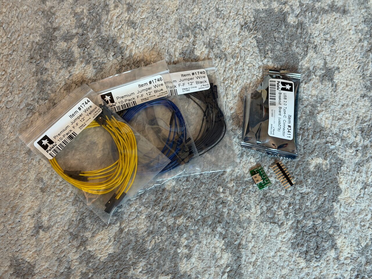
Required Parts:
- Pololu USB-C Breakout Board (but you could use the Adafruit board as well).
- Pololu Female Header Jumper Wires - I’ve used the Pololu 12” wires. But these Adafruit ones or others would be fine.
- USB 3.1 USB-C extension - USB 3.1 is actually important here because most USB-C cables don’t wire the SBU pins!
- Male pin headers for the board you’ll be connecting to.
Hardware Tools:
- A soldering iron and solder.
- Wire strippers.
Software Tools:
- A computer with VS Code, Python, and git available.
- A tutorial available to help with getting PlatformIO set up (such as Seeed Studio MeshCore Source Tutorial).
- Some patience!
Optional Stuff:
- Multimeter for testing voltage from the wiring.
- 3D printer if you want to print my little housing.
- Small M2 plastic screws for the housing.
- Some Kapton or electrical tape to seal up the board if not printing a housing.
- Heatshrink tubing.
- Mesh wire loom.
Hardware
I cut the jumpers in half since I am making multiple adapters. If you are only making a single adapter for a single version of pack then you will only need 2 wires (the divider and ground).
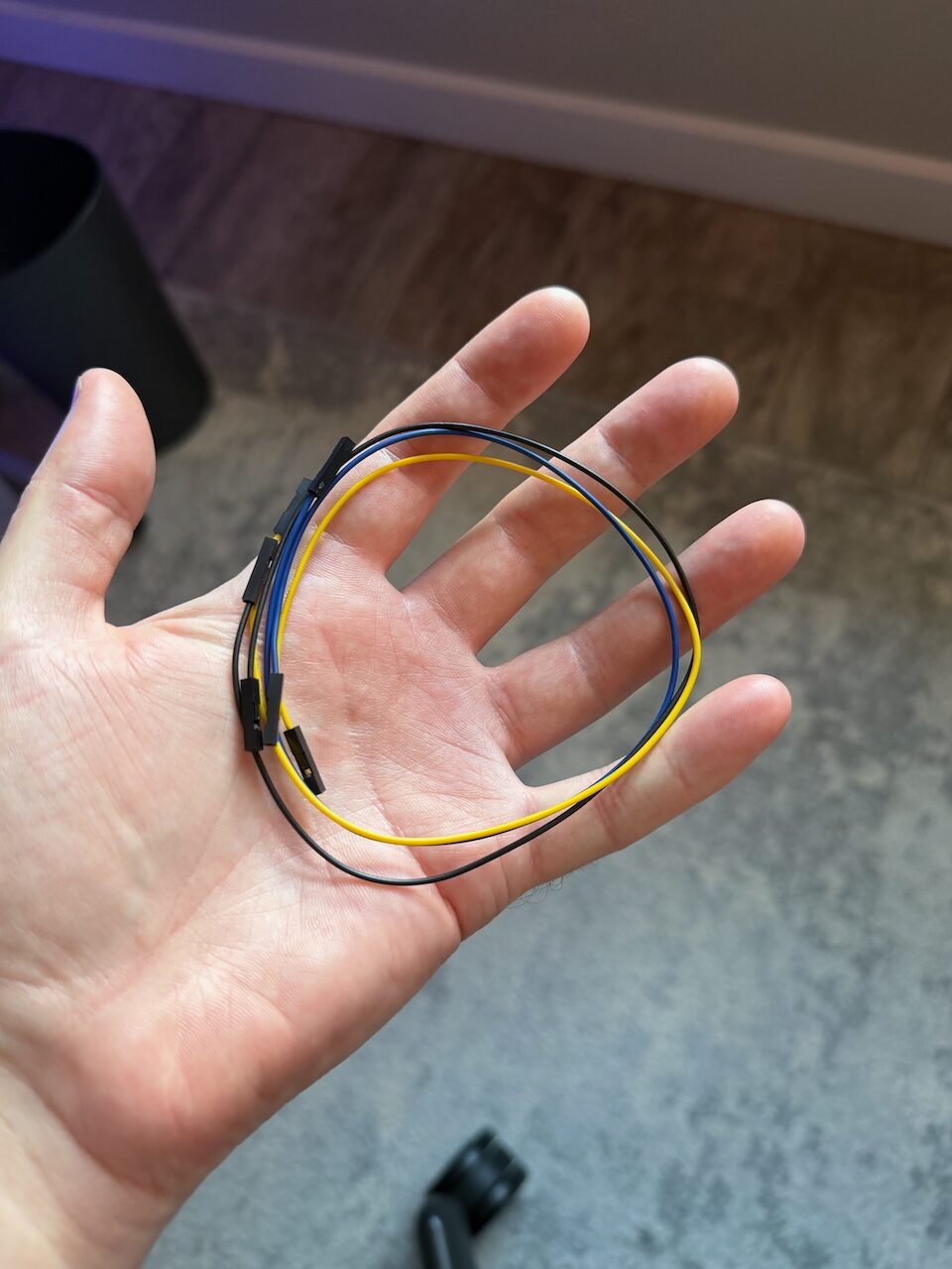
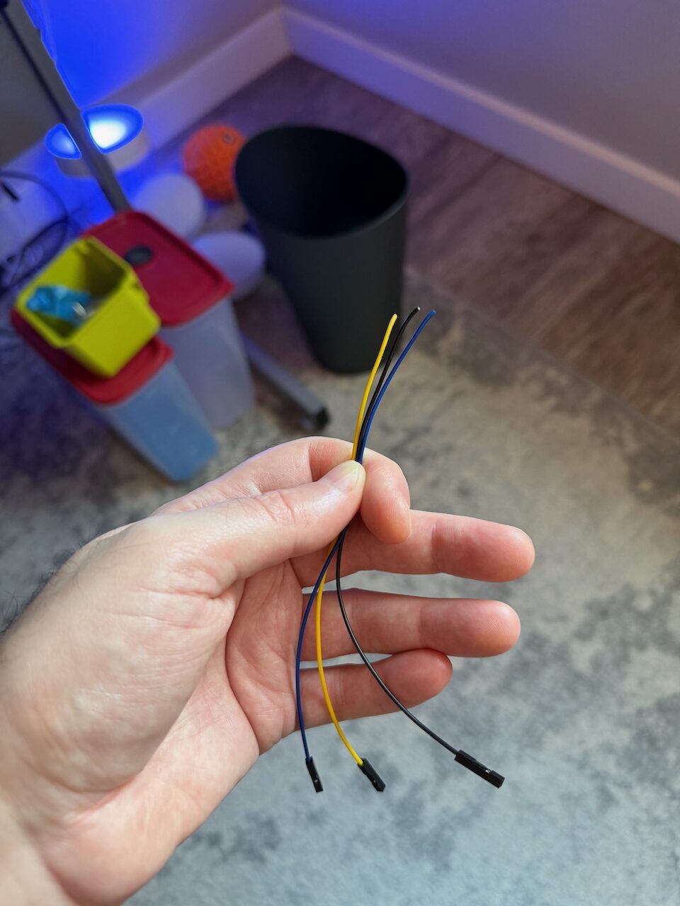
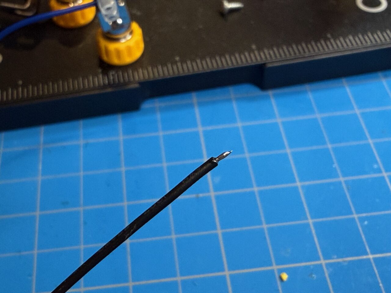
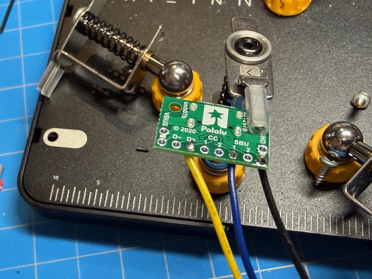
I stripped a very small bit off the wires and tinned them. Then solder them up to the USB-C breakout board. The important part here is that you solder up the correct pins for the Voltaic. The V1 (plastic case) battery packs use the D+ pin. The V2 (aluminum case) packs use the SBU pins (either SBU pin is fine). I’m using the yellow wire for V1 packs and blue for V2.
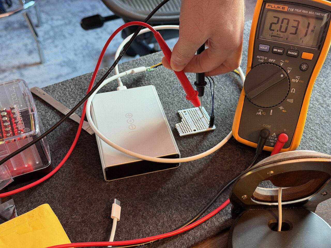
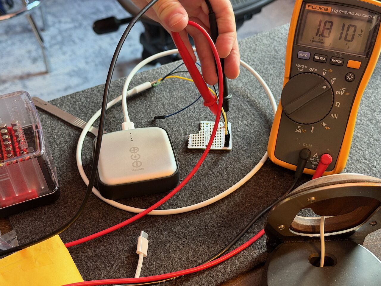
At this point you should be able to test the voltage divider from the pack. Make sure you are using a proper USB 3.1 cable if you are using a V2 pack or you’ll get nothing at all! Here you can see the V2 pack at 4 volts (using blue wire and ground) and the V1 pack at 3.6 volts (using yellow wire and ground). Multiply by two since that is the voltage divider inside the Voltaic.
Yes, that test breadboard has been through some stuff! ;)
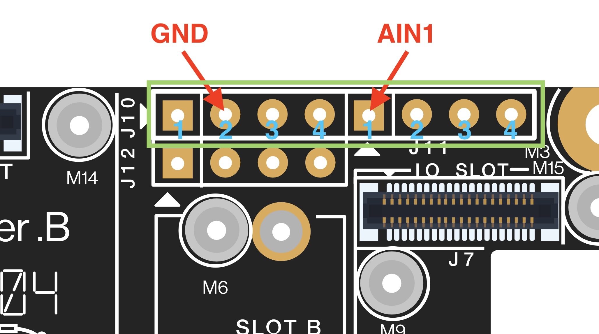
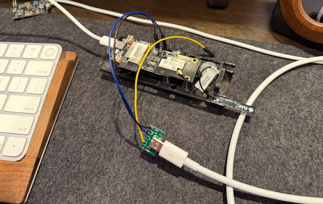
I’m using a RAK19007 as a testbed. You’ll need to solder the headers onto J10 and J11. We’re using pin #2 on J10 (which is ground) and pin #1 on J11 (which is the analog input pin AIN1).
Software
Both MeshCore and Meshtastic read battery voltage from an analog pin. That pin is usually baked into the specific board’s configuration. I’ll use MeshCore as an example on how we can change the pin to the external AIN1 that we used on the RAK19007.
In MeshCore the RAK4631 pins are set in variants/rak4631/RAK4631Board.h. PIN_VBAT_READ is the analog pin and ADC_MULTIPLIER is the multiplier. We need to wrap PIN_VBAT_READ and ADC_MULTIPLIER in #ifndef guards so they can be redefined in our new custom environment. MeshCore PR #3328 wraps them in #ifndef guards but until that gets merged we need to manually make these changes locally:
--- a/variants/rak4631/RAK4631Board.h
+++ b/variants/rak4631/RAK4631Board.h
@@ -5,8 +5,12 @@
 #include <helpers/NRF52Board.h>

 // built-ins
-#define  PIN_VBAT_READ    5
-#define  ADC_MULTIPLIER   (3 * 1.73 * 1.187 * 1000)
+#ifndef PIN_VBAT_READ
+  #define  PIN_VBAT_READ    5
+#endif
+#ifndef ADC_MULTIPLIER
+  #define  ADC_MULTIPLIER   (3 * 1.73 * 1.187 * 1000)
+#endif

 class RAK4631Board : public NRF52BoardDCDC {
 protected:
The same treatment goes to variants/rak4631/variant.h, which pins the LPCOMP channel used to wake the board back up from SYSTEMOFF when the battery recovers. That comparator watches a specific ADC channel, so it has to follow the sense pin:
--- a/variants/rak4631/variant.h
+++ b/variants/rak4631/variant.h
@@ -109,8 +109,12 @@ extern "C"
 #define PWRMGT_VOLTAGE_BOOTLOCK 3300   // Won't boot below this voltage (mV)
 // LPCOMP wake configuration (voltage recovery from SYSTEMOFF)
 // AIN3 = P0.05 = PIN_A0 / PIN_VBAT_READ
-#define PWRMGT_LPCOMP_AIN 3
-#define PWRMGT_LPCOMP_REFSEL 4  // 5/8 VDD (~3.13-3.44V)
+#ifndef PWRMGT_LPCOMP_AIN
+  #define PWRMGT_LPCOMP_AIN 3
+#endif
+#ifndef PWRMGT_LPCOMP_REFSEL
+  #define PWRMGT_LPCOMP_REFSEL 4  // 5/8 VDD (~3.13-3.44V)
+#endif

 // Other pins
 #define PIN_AREF (2)
With those guards in place, everything moves into platformio.local.ini.
We want P0.31 (WB_A1, which is AIN1 on J11). The Voltaic pack has its own divider so the multiplier has to change too. MeshCore PR #3328 wraps them in #ifndef guards.
Here is an example for the RAK4631 on the RAK19007 main board:
[env:RAK_4631_repeater_vbat_wb_a1]
extends = rak4631
build_flags =
  ${rak4631.build_flags}
  -D PIN_VBAT_READ=WB_A1
  -D PWRMGT_LPCOMP_AIN=7
  -D ADC_MULTIPLIER='(2 * 3.6 * 1000)'
  -D DISPLAY_CLASS=SSD1306Display
  -D ADVERT_NAME='"RAK4631 Repeater"'
  -D ADVERT_LAT=0.0
  -D ADVERT_LON=0.0
  -D ADMIN_PASSWORD='"password"'
  -D MAX_NEIGHBOURS=50
build_src_filter = ${rak4631.build_src_filter}
  +<helpers/ui/SSD1306Display.cpp>
  +<../examples/simple_repeater>
Everything from DISPLAY_CLASS down is just normal repeater configuration. Change the advert name, coordinates, and admin password to yours. The three that matter here are PIN_VBAT_READ, PWRMGT_LPCOMP_AIN, and ADC_MULTIPLIER. Save this to platformio.local.ini as a new file in the git clone root then build it like any other target:
pio run -e RAK_4631_repeater_vbat_wb_a1 -t upload
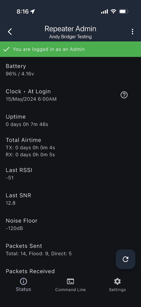
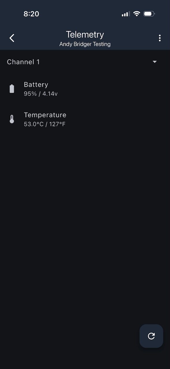
The repeater now reports the pack voltage instead of the onboard battery pin!
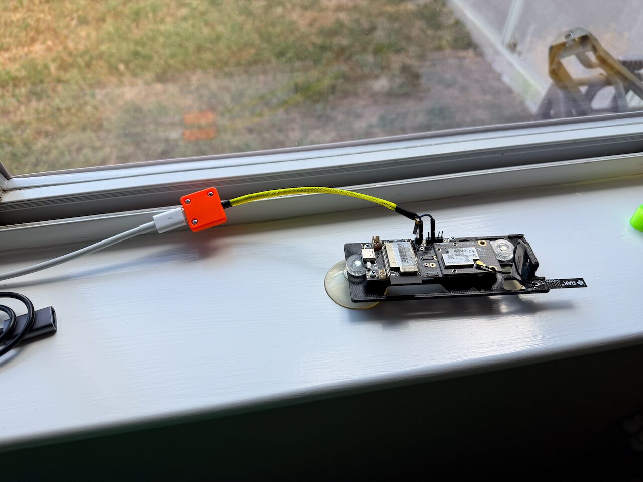
If you want to get fancy you can wrap up the adapter in a 3D printed case and some wire loom.
Thanks for reading!